Structural analysis of a new lift tower to be built on Power Plant site
A new lift tower was to be designed and to be fixed to an existing stair case connected to a boiler’s structure.
Several three dimensional FEM models were developed for the lift tower’s sensitivity analysis using software package Robot™ Structural Analysis Professional 2013, by Autodesk®. The main differences between the models were the support conditions on the side of the existing stair case (connection points for the walkways). Each model represented an attempt to simulate in a realistic way the stiffness of the stair case structure and its influence on the stress distribution of the lift tower’s structure. Fully pinned, fully released and non-linear gap supports were tested.
In order to have a structural system for the lift tower that was not excessively dependent on the support provided by the stair case, nor to create unacceptable strain on the foundation anchor bolts, final design was based on a non-linear gap support model for one direction. The resulted stress distribution on the steel profiles proved to be adequate and reasonable.
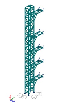
Figure 1
Load cases and combinations were the same for every model and both service and ultimate limit states were verified. Figure 1 shows an image of the final design model, which was also used for the structure’s dynamic analysis. Natural frequencies and vibration modes configuration were determined and excessive vibration risk was assessed.
As shown in Figure 1, a continuous truss bracing was considered along every side of the structure, being interrupted only when doors existed (floor and walkways levels). This allowed for the consideration of pinned supports to simulate the connection of the steel columns to the concrete foundation.
In order to check the need to reinforce the existing stair case structure, a simplified model of this structure was created and support reactions obtained with the lift tower’s model were applied as load cases. This allowed the evaluation of the stress increase on the steel profiles. Figure 2 shows an image of this model.
The structure was verified according to the applicable structural Eurocodes and CEB design guides, as referred before in section 2. Static and dynamic calculations were performed.
- EN 1990-1:2010 – Eurocode 0: Basis of Structural Design;
- EN 1991-1:2009 – Eurocode 1: Actions on Structures;
- EN 1993-1-1:2010 – Eurocode 3: Design of Steel Structures (Part 1-1: General Rules);
The lift tower structure was designed according to the stability and serviceability criteria proposed by EN 1993-1-1:2010.
Ultimate limit state analysis was performed for the following limits:
- Cross-section resistance: tension, compression, bending moment, shear, torsion and every applicable interaction;
- Buckling resistance of members;
- Lateral and lateral torsional buckling of structural components.
Connection design was done as per EN 1993-1-8:2010. Foundation anchor bolts design also complied with the requirements of the CEB design guide of fastenings on concrete.
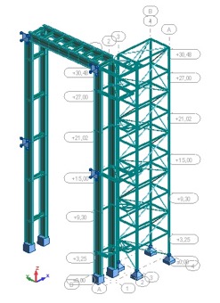
Figure 2
Serviceability limit state was verified imposing a maximum value for the deflection of the tower at the top, according to EN 1993-1-1:2010.
The results obtained with the simplified model of the existing structure showed that the staircase by itself was too flexible to endure the reactions from the lift tower’s walkways. So, the connection of the staircase structure to the rigid moment frames of the boiler’s structure was of the utmost importance. This connection, through braced elements, helped to reduce the staircase displacements when horizontal forces act. Lower displacements meaning lower induced stress.
Stress analysis results showed that, for wind loads combination, maximum induced stresses on the staircase were located in the areas of the staircase where no diagonal bracing exists (near doors and walkways). In order to reduce induced stress, some additional connections to the boiler’s structure were proposed.
The performed dynamic analysis showed that there were neither risk of galloping nor flutter phenomena due to wind loads. Nevertheless, the risk of vortex shedding related vibrations was analyzed, according to Annex E of Eurocode 1 Part 1-4. The amplitude of such vibrations was usually low, but could be still upsetting in an elevator tower. Since the risk of vibration was negligible, no preventive action or design modification was undertaken.
Regarding the stress increase on the stair case structure, induced by the linking walkways supports, the results showed that it was recommended to include some additional diagonal bracings, in order to make more effective the connection to the stiff moment frames of the boiler’s structure and thus reduce additional stress due to wind loads acting on the lift tower’s structure.